Bayaanka Asturnaanta
Tusaale ahaan.: NSO4GU3AB
Gaadiidka: Ocean,Air,Express,Land
Nooca Bixinta: L/C,T/T,D/A
Madadaalo: FOB,EXW,CIF
4GB 1600mhz 240-Pin dr3 udimm
Taariikhda dib u eegista
|
Revision No. |
History |
Draft Date |
Remark |
|
1.0 |
Initial Release |
Apr. 2022 |
|
![]()
Amarka miiska macluumaadka
|
Model |
Density |
Speed |
Organization |
Component Composition |
|
NS04GU3AB |
4GB |
1600MHz |
512Mx64bit |
DDR3 256Mx8 *16 |
Sifo
Hengstar oo xumaatay DDR3 SDRAM SHRIMS (Xaddidal Labanlaab oo Labanlaab ah Ns04gu3b waa 512m x 64-bit laba darajo 4GB DDR3-1600 CLBB DR11 1.5v SDRAM-ka SPD waxaa loo soo bandhigayaa Jedec Standard Standards DRR3-1600 Waqtiga 11-11-11 At 1.5V. 240-pin-pin-ka kasta wuxuu adeegsadaa faraha taabashada dahabka. SDRAM-ka SDRAM-ka ee loo yaqaan 'Digm' waxaa loogu talagalay in loo isticmaalo xusuusta ugu weyn markii lagu rakibay nidaamyada sida PC-yada iyo shaqooyinka.
Astaamaha
Bixi: VDD = 1.5V (1.425v illaa 1.575v)
vddq = 1.5v (1.425v illaa 1.575v)
800mhz FCK oo loogu talagalay 1600MB / seker / PIN
8 Bank gudaha ah oo madaxbanaan
romareraftabled CASTIS: 11, 10, 9, 8, 7, 6
Daahitaanka isku darka ah ee 'Lightiff': 0, CL - 2, ama CL - 1 saac
8-bit pre-pretch
Dhererka 'burst dherer'
bi-TONTAL ISTICMAALO XUQUUQDA
Dib u habeynta (iskiis) hagaajinta; Qiyaasta is-dhexgalka gudaha iyada oo loo marayo ZQ PIN (RZQ: 240 ohm ± 1%)
on u dhinta joojinta iyadoo la adeegsanayo ODT PIN PIN
average waqti ka fogaan 7.8us ka hooseeya tjarka 85 ° C, 3.90 ° C <95 ° C <95 ° C
ynchronous Reset
Dib-u-soo-nooleynta-soo-saarka
fly-by topology
PCCB: Dherer 1.18 "(30mm)
roohs waafaqsan oo halogen-bilaash ah
Cabirrada waqtiga muhiimka ah
|
MT/s |
tRCD(ns) |
tRP(ns) |
tRC(ns) |
CL-tRCD-tRP |
|
DDR3-1600 |
13.125 |
13.125 |
48.125 |
2011/11/11 |
Miiska cinwaanka
|
Configuration |
Refresh count |
Row address |
Device bank address |
Device configuration |
Column Address |
Module rank address |
|
4GB |
8K |
32K A[14:0] |
8 BA[2:0] |
2Gb (256 Meg x 8) |
1K A[9:0] |
2 S#[1:0] |
Sharaxaada PIN
|
Symbol |
Type |
Description |
|
Ax |
Input |
Address inputs: Provide the row address for ACTIVE commands, and the column |
|
BAx |
Input |
Bank address inputs: Define the device bank to which an ACTIVE, READ, WRITE, or |
|
CKx, |
Input |
Clock: Differential clock inputs. All control, command, and address input signals are |
|
CKEx |
Input |
Clock enable: Enables (registered HIGH) and disables (registered LOW) internal circuitry |
|
DMx |
Input |
Data mask (x8 devices only): DM is an input mask signal for write data. Input data is |
|
ODTx |
Input |
On-die termination: Enables (registered HIGH) and disables (registered LOW) |
|
Par_In |
Input |
Parity input: Parity bit for Ax, RAS#, CAS#, and WE#. |
|
RAS#, |
Input |
Command inputs: RAS#, CAS#, and WE# (along with S#) define the command being |
|
RESET# |
Input |
Reset: RESET# is an active LOW asychronous input that is connected to each DRAM and |
|
Sx# |
Input |
Chip select: Enables (registered LOW) and disables (registered HIGH) the command |
|
SAx |
Input |
Serial address inputs: Used to configure the temperature sensor/SPD EEPROM address |
|
SCL |
Input |
Serial |
|
CBx |
I/O |
Check bits: Used for system error detection and correction. |
|
DQx |
I/O |
Data input/output: Bidirectional data bus. |
|
DQSx, |
I/O |
Data strobe: Differential data strobes. Output with read data; edge-aligned with read data; |
|
SDA |
I/O |
Serial |
|
TDQSx, |
Output |
Redundant data strobe (x8 devices only): TDQS is enabled/disabled via the LOAD |
|
Err_Out# |
Output (open |
Parity error output: Parity error found on the command and address bus. |
|
EVENT# |
Output (open |
Temperature event: The EVENT# pin is asserted by the temperature sensor when critical |
|
VDD |
Supply |
Power supply: 1.35V (1.283–1.45V) backward-compatible to 1.5V (1.425–1.575V). The |
|
VDDSPD |
Supply |
Temperature sensor/SPD EEPROM power supply: 3.0–3.6V. |
|
VREFCA |
Supply |
Reference voltage: Control, command, and address VDD/2. |
|
VREFDQ |
Supply |
Reference voltage: DQ, DM VDD/2. |
|
VSS |
Supply |
Ground. |
|
VTT |
Supply |
Termination voltage: Used for control, command, and address VDD/2. |
|
NC |
– |
No connect: These pins are not connected on the module. |
|
NF |
– |
No function: These pins are connected within the module, but provide no functionality. |
Qoraallada : Shaxda sharraxa PIN-ka ee hoose waa liis dhameystiran oo ku saabsan dhammaan biinanka suurtagalka ah ee dhammaan cutubyada DDR3. Dhamaan biinanka ku taxan May Lama taageerin cutubkan. Ka eeg meeleynta PIN si aad u hesho macluumaadka gaarka ah ee cutubkan.
Jaantuska shaqada ee shaqeeya
4GB, 512mx64 module (2rank of x8)


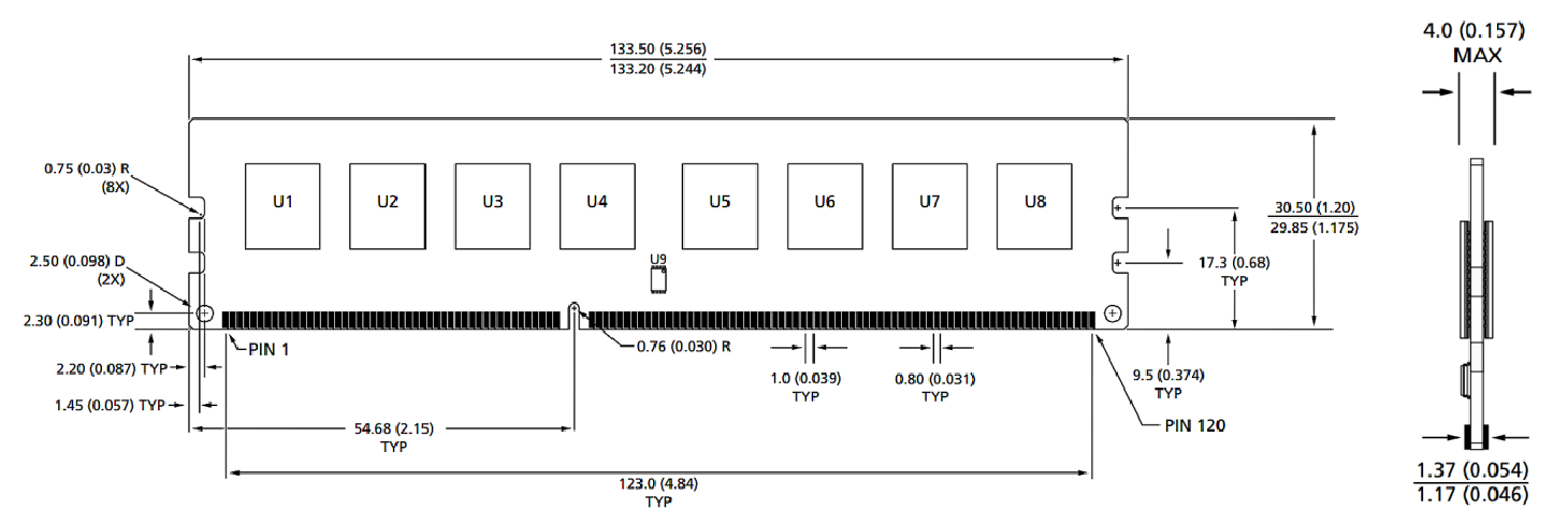
Cabirrada module
Aragtida hore

Aragtida hore

Ogeysiis:
1.Qaar cabirku waxay ku jiraan milimitir (inji); Max / Min ama Mine (Tirti) halka lagu xusay.
2.Toleler oo ku saabsan dhammaan cabirrada ± 0.15mm haddii aan si kale loo cayimin mooyee.
3. Jaantuska cabbirka ayaa loo tixraacayaa tixraac oo keliya.
Qaybaha alaabta : Qalabka loo yaqaan 'wers smart'


Bayaanka Asturnaanta

Buuxi macluumaad dheeri ah si markaa si dhakhso leh ula xiriiri karto
Bayaanka Asturnaanta